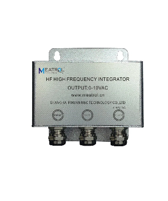
HF High Frequency integrator HF
is a High Frequency Rogowski coil integrator, in a compact shield
aluminium alloy enclosure, powered directly from the mains.It is
providing the measurement of all kinds of waveforms like 3/5μs,
8/20μs,10/350μs,frequencyfrom 100kHz to 1MHz, it also features in
direct connection to oscilloscopeWhat does Integrator do?• Rogowski
coil output is weak voltage mV signal,HF has ability to amplify and
convert it to standard signal which could be catched by multimeter
and scope.• Rogowski coil output is proportional tothe frequency of
the measured current, the signalequalization ensure a linear
response on a widefrequency range. TP allows to use coils on
differentelectrical network frequencies, keeping the sameoutput
level over the frequencies.•An integrator is essential to equalize
and shift by 90° the output signal from the Rogowski coils. It
consists of an activeelectronic circuit with negligible offset and
a good linearity.FeatureTP can be combined with any model and size
of Y-FCT or FCT Rogowski coils.The available values are: 0-12V
peakOn request the input value can be customized according to the
application.TP and Rogowski coil is a very flexible system,
suitable for high power load analysis, impulsivecurrent monitoring,
DC ripple measurement, etc.Due to its specific features, flexible
Rogowski coil is an extremely comfortable solution for current
measurement and can be used in a number of cases where traditional
current transducer is not the adequate solution.Advantage• High
read accuracy 2% • Wide power supply arrange:4-12VDC•
1/5μs,8/20μs,10/350μs waveform restore•Up to 500kA lightning
current measurementRelated ProductsH-FCT
ApplicationsMeasuring devices, lab instrumentation•Lightning
protection• Lightning monitoring•Lightning current measurement•
Pulse waveform analysis What is a Rogowski coil?Rogowski
coils have been used for the detection and measurement of electric
currents for decades. They are based on a simpleprinciple: an
"air-cored" coil is placed around the conductor in a toroidal
fashion and the magnetic field produced by the current induces a
voltage in the coil. The voltage output is proportional to the rate
of change of current. This voltage is integrated, thus producing
anoutput proportional to the current.By using precision winding
techniques, especially developed for the purpose, the coils are
manufactured so that their output is notinfluenced by the position
of the conductor within the toroid, and to reject interference from
external magnetic fields caused, for example, from nearby
conductors.Basically, a Rogowski coil current measuring system
consists of a combination of a coil and conditioning
electronics.Rogowski coil current transducers are used for the AC
measurement.They can be used in similar circumstances to current
transformers but for many applications they have considerable
advantages:• Wide dynamic range.• High linearity.• Very useful with
large size or awkward shaped conductors or in places with limited
access. Thanks to the structure without hardcore, the coil
can be easily manufactured according to
the application or to the available space.• Unlike traditional
current transducers, there is no danger from open-circuited
secondaries.• They cannot be damaged by large overloads.• They are
non-intrusive. They draw no power from the main circuit carrying
the current to be measured.• They are also light weighted and in
some applications are light enough to be suspended on the conductor
being measured.The transducer does not measure direct currents but,
unlike a current transformer, it can carry out accurate
measurements of ACcomponent even if there is a large superimposed
DC component, since there is no iron core causing saturation. This
feature isparticularly useful for measuring ripple currents for
example in battery charging systems.Specification
ModelHFRated output1V AC peakMaximum Output(overload)12V AC
peak Rated ratio1kA/1V10kA/1V50kA/1VMinimum
ratio:1000A/1VRead Accuracy2% typical at 10% to 1000% of rated
Current @25ºCPhase error≤0.5°Linearity±0.5% of reading(10% to 1000%
of range)Minimum Current measurement10% of rated ratioTypical
waveform 1/5μs,8/20μs,10/350μsResponse time≤1usPower
consumption300mWOutput on 0A (zero
drift)≤10mVTemperature
drift200ppm/ºCWeight160gDimension86*90*29mmPower supply4-12V DC
(included 85-265AC to 12V DC adaptor)Operating temperature-20ºC to
70ºCStorage temperature-30ºC to 90ºCRelative humidity80%
max.without condensationProtection degreeIP20Terminal(Locks
type) Input:locked with H-FCT signal
cableOutput:BNC female terminal with 2m BNC male terminal cable
Power:DC-DC terminal 5.5*2.0mm² with 85-265VAC
adaptor Other requirements, please contact us to OEM.Actual
waveform showTest Equipment:
8/20 test waveform
Transient
current waveform


Quality Compact Shield Aluminium Alloy Enclosure High Frequency Rogowski Coil Integrator Current Converter products, provide good price Compact Shield Aluminium Alloy Enclosure High Frequency Rogowski Coil Integrator Current Converter from .
Related products about Compact Shield Aluminium Alloy Enclosure High Frequency Rogowski Coil Integrator Current Converter
-
 Waste Tyre Plastic Recycling Machinery Machine Tire Crusher Production Line Rubber Crumb Grinding Machine Equipment Tire Shredder
-
 Stretch Plastic Blowing Pet Bottle Making Blow Molding Machine Bottles Stretch Automatic Pet Bottle Blowing Machine
-
 Waste Plastic Pet Bottle, Water Bottle Flake, PP/HDPE/LDPE PE Film Jumbo Woven Bags Plastic Crusher Machine, Plastic Crushing Washing Recycling Machine
-
 Type 2 Wall-Mounted Electric Car Charging Station 7kw /11 Kwelectric Vehicle Charging Station Home Wallbox AC EV Charger Single Phase or 3three Phase
-
 G-View G12W Wholesale Auto Car LED Headlight Bulb High Power H13 H11 9005 H7 H4 Car LED Headlights LED Car Lights
-
 New Design Porcelain Round Plates Dinner Set for Wedding and Banquet
-
 China 2023 New Design Super Soft 100% Polyester Microfiber Knitted Oversized Decoration Hoodie Blanket
-
 Handmade Art Creative Materials Thickened White Paper Cup DIY Disposable Handmade Colored Paper Cup