Center Break Isolator and double Break Isolator These
disconnectors are , no load switching devices which physically
isolate the lines. They are designed for horizontal outdoor
application and can also be designed for vertical installation. For
earthing and closing of switchyard portions of the installation,
the earthing switches are provided on disconnector. If required.
The following documents were referred to during the preparation of
this specification. In case of conflict, the provisions of this
specification shall take precedence. IEC 129:1975: Alternating
Current Disconnectors (Isolators) and Earthing Switches IEC
60694:2002: Common Specifications for High Voltage Switchgear and
Controlgear BS 729: Hot dip galvanized coating on iron and steel
articles IEC62271-102 Isolator (Disconnector) - a mechanical
switching device which provides, in the open position, an isolating
distance in accordance with Electrical Safety requirements. SERVICE
CONDITIONS The isolator shall be suitable for continuous operation
outdoors in tropical areas at altitudes of up to 2200m above sea
level, humidities of up to 90%, average ambient temperature of
+30ºC with a minimum of -1ºC and a maximum of +40ºC and heavy
saline conditions along the coast. 4.2. DESIGN AND CONSTRUCTION
4.2.1 The Isolator, Solid Link shall be designed and constructed in
accordance with IEC 129 and IEC 60694. 4.2.2 The isolating link
shall be of the vertical opening, designed for single phase manual
operation. It shall be easily removed and replaced by using a
portable operating rod. 4.2.3 The isolating link shall incorporate
double porcelain insulators to suit voltage requirements and
mounted on hot dipped galvanised steel under base suitable for
vertical mounting. 4.2.4 The isolating link shall be arranged so
that each unit is mounted independently on an angle bracket. It
shall be supplied complete with the angle bracket and accessories
suitable for mounting on 'U' type steel channel. The drawings to be
submitted shall indicate all the applicable mounting positions.
4.2.5 The isolator shall be designed such that in fully open
position, it shall provide adequate electrical isolation between
the contacts on each phase. It shall conform to the requirement as
single point isolation for safety. 4.2.6 All steel parts shall be
hot dip galvanized to BS 729. The minimum coating of galvanizing
required is 80 microns. 4.2.7 The solid link shall be removable
from the mounting by use of operating rod. 4.2.8 All current
carrying parts of the isolator shall be made of high conductivity
material. 4.2.9 The isolator shall be fitted with clamp connectors
for Aluminium (ACSR) conductor of Aluminium (ACSR)conductor of
up to 18.2mm diameter. The rating of the complete isolator shall be
as follows: - Rated voltage 36 kV Rated frequency 50 Hz Rated
lightning impulse withstand voltage 200 kV Rated power frequency
withstand voltage, dry 95 kV Rated normal current 400 Amps Rated
short time withstand current for 3 sec, min. 18.0 kA Minimum
creepage distance of insulators 900 mm /* January 22,
2024 19:08:37 */!function(){function s(e,r){var
a,o={};try{e&&e.split(",").forEach(function(e,t){e&&(a=e.match(/(.*?):(.*)$/))&&1


Quality Air Break Swich Isolator Disconnector Switch 11kv products, provide good price Air Break Swich Isolator Disconnector Switch 11kv from .
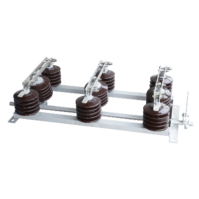
Larger photo of Air Break Swich Isolator Disconnector Switch 11kv
Related products about Air Break Swich Isolator Disconnector Switch 11kv
-
 Waste Tyre Plastic Recycling Machinery Machine Tire Crusher Production Line Rubber Crumb Grinding Machine Equipment Tire Shredder
-
 Stretch Plastic Blowing Pet Bottle Making Blow Molding Machine Bottles Stretch Automatic Pet Bottle Blowing Machine
-
 Waste Plastic Pet Bottle, Water Bottle Flake, PP/HDPE/LDPE PE Film Jumbo Woven Bags Plastic Crusher Machine, Plastic Crushing Washing Recycling Machine
-
 Type 2 Wall-Mounted Electric Car Charging Station 7kw /11 Kwelectric Vehicle Charging Station Home Wallbox AC EV Charger Single Phase or 3three Phase
-
 G-View G12W Wholesale Auto Car LED Headlight Bulb High Power H13 H11 9005 H7 H4 Car LED Headlights LED Car Lights
-
 New Design Porcelain Round Plates Dinner Set for Wedding and Banquet
-
 China 2023 New Design Super Soft 100% Polyester Microfiber Knitted Oversized Decoration Hoodie Blanket
-
 Handmade Art Creative Materials Thickened White Paper Cup DIY Disposable Handmade Colored Paper Cup