Main characteristicsThe buckle structure is fixed and the stability
is good Adopt high magnetic permeability core, good linearity and
high sensitively Terminal output, easy to stallApplicationsRural
power grid reconstruction project Online environmental monitoring
Smart fire-fighting power consumption Smart power consumption
system Power quality analysis and electrical equipment signal
collectionElectrical parametersTypeTRFK-36CRated primary
current200A~600ARated secondary current1A,5AOverload1.2 timesRated
capacity1VA, 2.5VA,3.75VAAperture36mmRatio error@rated
primary±0.5%, ±1.0%Phase error@rated primary≤60′Working
frequency50/60 HzRms voltage for AC isolation test(between primary
and secondary) 3kV AC/1mA 10sRelative humidity≤90%Operating
ambient temperature-25ºC~+75ºCStorage
temperature-40ºC~+85ºCBarometric condition70kpa~106kpaApplication
placeIndoor useSecondary output typeTerminal outputWeightAround
580gAccuracy parametersInput
current(A)1%In5%In20%In100%In120%InRatio
error(%)-±1.5±0.75±0.5±0.5Phase error(′)-≤180≤90≤60≤60Such as the
specification is 200A/5A, When the input current is 200A, S1 and S2
as the output, S1 is connected to S3 in parallel, and S2 is
connected to S4 in parallel. When the input current is 400A, S1 and
S4 as output, S2 and S3 are connected in series.Installation
instructionsWarning: Please use professional and appropriate
protective equipment to prevent electric shock and ensure
safety.Installation stepsStep1. Before installing, ensure that the
circuit is in the state of power failure, or live installation
operation, professional personnel are required.Step 2. Open the
protective cover of current transformer, connect the wire with the
terminal output of the current transformer and connect it to the
port of the measuring equipment, and ensure the circuit is closed.
See Figure 1.Step 3. Open the transformer latch and prepare for
installation. See Figure 2.Step 4. Place the cable inside the hole
of current transformer. Ensure that the current direction of the
cable is consistent with the arrow on the current transformer. Lock
the latch again, and fix the cable with the nylon ties to hook both
ends of the transformer to prevent sliding. See Figure 3.
Winding parallel connection method
Winding series
connection method
Fig.1 Connect S1, S2, S3 and S4 with special cables according to
the requirements of customers
Winding parallel connection method
Winding series connection method
Fig.2 Open the latch and run through the
cable Winding parallel
connection method
Winding series connection method
Fig.3 Lock the latch, and fix the cable using
a nylon tie /* January 22, 2024 19:08:37
*/!function(){function s(e,r){var
a,o={};try{e&&e.split(",").forEach(function(e,t){e&&(a=e.match(/(.*?):(.*)$/))&&1
Quality Tr Split Core Open Type AC/DC Current Transformer Sensor 200A/300A/400A/500A/1A 0.5 products, provide good price Tr Split Core Open Type AC/DC Current Transformer Sensor 200A/300A/400A/500A/1A 0.5 from .
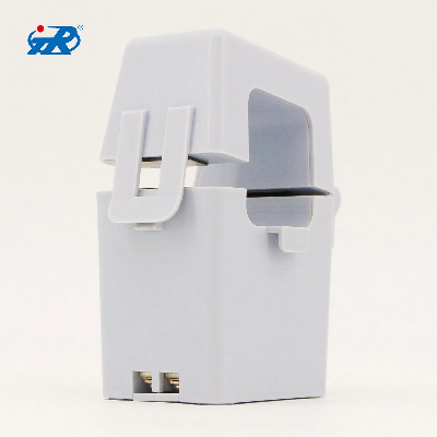
Larger photo of Tr Split Core Open Type AC/DC Current Transformer Sensor 200A/300A/400A/500A/1A 0.5
Related products about Tr Split Core Open Type AC/DC Current Transformer Sensor 200A/300A/400A/500A/1A 0.5
-
 Waste Tyre Plastic Recycling Machinery Machine Tire Crusher Production Line Rubber Crumb Grinding Machine Equipment Tire Shredder
-
 Stretch Plastic Blowing Pet Bottle Making Blow Molding Machine Bottles Stretch Automatic Pet Bottle Blowing Machine
-
 Waste Plastic Pet Bottle, Water Bottle Flake, PP/HDPE/LDPE PE Film Jumbo Woven Bags Plastic Crusher Machine, Plastic Crushing Washing Recycling Machine
-
 Type 2 Wall-Mounted Electric Car Charging Station 7kw /11 Kwelectric Vehicle Charging Station Home Wallbox AC EV Charger Single Phase or 3three Phase
-
 G-View G12W Wholesale Auto Car LED Headlight Bulb High Power H13 H11 9005 H7 H4 Car LED Headlights LED Car Lights
-
 New Design Porcelain Round Plates Dinner Set for Wedding and Banquet
-
 China 2023 New Design Super Soft 100% Polyester Microfiber Knitted Oversized Decoration Hoodie Blanket
-
 Handmade Art Creative Materials Thickened White Paper Cup DIY Disposable Handmade Colored Paper Cup


