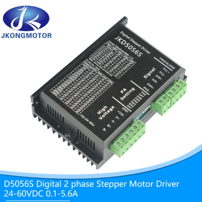
0.1-5A 24-50V Stepper Motor Driver for NEMA23 Stepper
Motor1. Electrical indicators of NEMA23 stepper motor
driver InstructionJKD5056SMinimumTypicalMaximumUnitThe output
current0.1-5.0AInput voltage243650VDCControl signal input
current61016mAControl signal interface level4.5528VdcInput signal
minimum pulse width1.5--usStepper pulse frequency0-200KHzInsulation
resistance100 MΩ 2. Using environment and
parameters of nema23 2phase stepper motor Cooling
methodNatural cooling or forced air coolingUsing
environmentoccasionCan not be placed next to other heating
equipment, should avoid dust, oil mist, corrosive gas, too big
humidity and strong vibration place, prohibit to have combustible
gas and conductive dusttemperature-5ºC ~ +50ºChumidity40 ~
90%RHvibration5.9m/s2MAXStorage temperature-20ºC~80ºCUsing
altitudeBelow 1000 metresWeightAbout 280 g 3. Mechanical
installation diagram Interface description1) Control
signal interface circuit NameFunction PUL+Pulse
signal: pulse rising edge is effective; In PUL high level,voltage
is 4.5 ~ 28Vdc, and the low level, voltage is 0 ~ 0.5v. In order to
reliably respond to the pulse signal, the pulse width should be
greater than 1.5μs PUL- DIR+Direction signal: high/low
level signal, to ensure reliable commutation of motor, directional
signal should be established before the pulse signal at least 2μs.
The initial direction of the motor is connect to motor wiring,
change winding (e.g., A +, A - exchange) can change the direction
of the motor running, In DIR high level,the voltage is 4.5 ~ 28
VDC,in low level,voltage is 0 ~ 0.5 V. DIR- ENA+Enable
signal: this input signal is used to enable or prohibit. ENA+
connect 4.5 ~ 28Vdc, ENA- connect low level (or internal optical
coupling), the actuator will cut off the electrical current to keep
the motor in a free state and the stepper pulse is not responsive.
When this function is not required, the enable signal can be
suspended. ENA- 2) High voltage
interface NameFunction GNDDC power
grounding +VdcDC power positive, dc 20~50 VDC, recommended for
36Vdc. A+,A-Motor A phase coil interface B+,B-Motor B
phase coil interface 3) Status indicationGreen LED is
the power indicator, when the driver connect to the power supply,
the LED is light; When the driver cuts off the power, the LED is
off. The red LED is the fault indicator, and when there is a
failure, the indicator will blink in a cycle of three seconds. Red
LED is off when the fault is removed by the user. Red LED flashing
times in 3 seconds representing different fault
information. FAQ:Q1: Are you a trading company or a
manufacturer?A1: We are a manufacturer with 8 years of professional
production experience. Q2: Do you provide OEM or ODM
service?A2: Yes, JKONGMOTOR company warmly welcome OEM or ODM
corporrations and other companies to establish long-term
cooperation with us. Q3: What's the MOQ?A3: 3 units.
Q4:Where is your loading port?A5:Building A2,Hutan Industrial
Zone,Wujin District, Chagnzhou,China. Q5: Are your delivery
dates on time?A5: Yes of course.We have our own factory so can
ensure timely delivery. Q6: What about your warranty?A6: We
guarantee is 12 months, for sea order is 15 months.
Q7: Do you provide after-sales service?A7: Yes, we will give
useful advise within 12 hours if you have any requirments./*
January 22, 2024 19:08:37 */!function(){function s(e,r){var
a,o={};try{e&&e.split(",").forEach(function(e,t){e&&(a=e.match(/(.*?):(.*)$/))&&1
Quality 0.1-5A 24-50V Stepper Motor Driver for NEMA23 Stepper Motor products, provide good price 0.1-5A 24-50V Stepper Motor Driver for NEMA23 Stepper Motor from .
Larger photo of 0.1-5A 24-50V Stepper Motor Driver for NEMA23 Stepper Motor
Related products about 0.1-5A 24-50V Stepper Motor Driver for NEMA23 Stepper Motor
-
 Waste Tyre Plastic Recycling Machinery Machine Tire Crusher Production Line Rubber Crumb Grinding Machine Equipment Tire Shredder
-
 Stretch Plastic Blowing Pet Bottle Making Blow Molding Machine Bottles Stretch Automatic Pet Bottle Blowing Machine
-
 Waste Plastic Pet Bottle, Water Bottle Flake, PP/HDPE/LDPE PE Film Jumbo Woven Bags Plastic Crusher Machine, Plastic Crushing Washing Recycling Machine
-
 Type 2 Wall-Mounted Electric Car Charging Station 7kw /11 Kwelectric Vehicle Charging Station Home Wallbox AC EV Charger Single Phase or 3three Phase
-
 G-View G12W Wholesale Auto Car LED Headlight Bulb High Power H13 H11 9005 H7 H4 Car LED Headlights LED Car Lights
-
 New Design Porcelain Round Plates Dinner Set for Wedding and Banquet
-
 China 2023 New Design Super Soft 100% Polyester Microfiber Knitted Oversized Decoration Hoodie Blanket
-
 Handmade Art Creative Materials Thickened White Paper Cup DIY Disposable Handmade Colored Paper Cup


