VB4 Indoor Vacuum Circuit BreakerDescriptionVB4 series medium
voltage vacuum circuit-breakers with lateral operating mechanism
feature the separate pole construction technique. VS1 vacuum
circuit breakers have been designed for indoor use and air
insulated switchboards. Their switching capacity is sufficient
to handle any conditions arising from switching of equipment and
system components under normal operating and fault conditions,
particularly short-circuits, within the parameters of their
technical data. The vacuum circuit-breakers of type VB4, designed
in column form, can be supplied both as individual units for fixed
installation and mounted on chassis. Vacuum circuit-breakers are
characterized by their simple and robust construction. They have
a long life expectancy. There is no adverse effect on the
vacuum, even from frequent switching of operating and short-circuit
currents. AdvantagesVacuum circuit-breakers have particular
advantages for use in networks where there is a high switching
frequency in the working current range and/ or where a certain
number of short- circuit breaking operations are expected. VS1
vacuum circuit- breakers are suitable for auto reclosing and have
exceptionally high operating reliability and long life. The
circuit- breakers are notable for their compact design, small
dimensions together with high capacity. The operating mechanisms
have a low maintenance requirement and the interrupters are
maintenance- free throughout their service lives. They are well
suited to all load breaking operations which occur in practice, and
in particular: Short-circuit currents; Overhead lines
under load and, no-load conditions; Cables under load and
no-load conditions; Transformers under load and no-load
conditions; Generators under load and no-load
conditions; Ripple control system; Capacitor banks(also
parallel switching) and Motors with starting currents above
600A; Fields of applicationBelow is the list of SM6 range
units used in MV/LV transformer substations and industrial
distribution substations: Cable control and protectionOverhead
control and protectionTransformers and distribution
substationsMotor and transformer control and protectionGenerator
control and protectionCapacitor bank control and protectionMain
characteristics1) Test voltage according DIN VDE 0670, part 1000,
list 22) 4000 A with forced cooling3) 3150 A with forced
cooling in AP technology4) Higher values on request5) 360 mm for
fixed, 280 mm for withdrawable Version6) Circuit-breaker with heat
sink 616 mm7) Withdrawable Version8) Circuit-breaker with heat sink
634
mm SerialNumberItemUnitData 31.5kA40kA50kA1Rated
voltageKv12/17.5/24kV2Maximum working voltageKv123Rated
currentA1250 16002000 25001250 16002500 31501250 2500 31504Rated
short-circuit break currentKA31.540505Rated short-circuit close
current (peak value)KA801001256Rated withstand current (peak
value)KA8010012574S Rated little withstand currentKA31.540508Rated
insulation levelIndustrial frequencyWithstand
voltageKA42/50/60Thunder impulseWithstand voltage75/95/1259Rated
operation order Off-0.3S on and off-180S-on and
off10Mechanical lifeTimes1000011Rated short-circuit current break
and close timeTimes5012Speak and move organization amountAssign the
curre t of the floodgate(DC) V11022013Speak and
move organization amountEqual to the curre t of the
floodgate(DC) V11022014Switching distance of the
contactmm>1115Ultra journey(touches the headSpringand compress
length)mm4+/-0.516Three-phase breaking into shutFloodgate sex of
the same periodMs
Quality Vb4-11kv/630A-25ka Vcb Draw-out Type Indoor Vacuum Circuit Breaker products, provide good price Vb4-11kv/630A-25ka Vcb Draw-out Type Indoor Vacuum Circuit Breaker from .
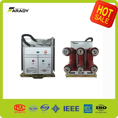
Larger photo of Vb4-11kv/630A-25ka Vcb Draw-out Type Indoor Vacuum Circuit Breaker
Related products about Vb4-11kv/630A-25ka Vcb Draw-out Type Indoor Vacuum Circuit Breaker
-
 Waste Tyre Plastic Recycling Machinery Machine Tire Crusher Production Line Rubber Crumb Grinding Machine Equipment Tire Shredder
-
 Stretch Plastic Blowing Pet Bottle Making Blow Molding Machine Bottles Stretch Automatic Pet Bottle Blowing Machine
-
 Waste Plastic Pet Bottle, Water Bottle Flake, PP/HDPE/LDPE PE Film Jumbo Woven Bags Plastic Crusher Machine, Plastic Crushing Washing Recycling Machine
-
 Type 2 Wall-Mounted Electric Car Charging Station 7kw /11 Kwelectric Vehicle Charging Station Home Wallbox AC EV Charger Single Phase or 3three Phase
-
 G-View G12W Wholesale Auto Car LED Headlight Bulb High Power H13 H11 9005 H7 H4 Car LED Headlights LED Car Lights
-
 New Design Porcelain Round Plates Dinner Set for Wedding and Banquet
-
 China 2023 New Design Super Soft 100% Polyester Microfiber Knitted Oversized Decoration Hoodie Blanket
-
 Handmade Art Creative Materials Thickened White Paper Cup DIY Disposable Handmade Colored Paper Cup


