ESP8266 4CH 5V WiFi Relay Module Smart Home Mobile APP Remote
Control Switch I. Overview The 5V
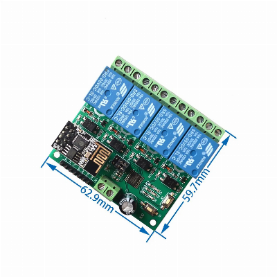
ESP8266 four-way WIFI relay module uses the ESP-01 as a WIFI
module, with a mature and stable 8-bit MCU chip. It can realize the
wireless control of the 4-way relay using the mobile phone APP
within the LAN in a simple configuration process. Second,
functional characteristics 1, Onboard high performance
microprocessor and ESP-01 WIFI module; 2, the module has 2
working modes: Mode 1: The mobile phone is directly mounted on
the WIFI module; Mode 2: The mobile phone and WIFI module are
loaded on the router at the same time; Additional features: It
can also be used as a USB relay when the ESP-01 is
unplugged. 3, transmission distance:(1) In the open
environment, the maximum stable transmission distance when the
mobile phone is mounted on the WIFI module is 100m;(2) When the
WIFI module and the mobile phone are mounted on the router at the
same time, the transmission distance is strong according to the
signal of the router.Weak and certain.4. Use Smartconfig technology
to complete the configuration of the ESP-01 WIFI module account and
password on the mobile phone APP. The configured account and
password have the power-off memory function.5, On-board 12V,
10A/250V AC 10A/30V DC relay, can continuously suck 100,000 times,
with diode escaping protection, short response time;6, onboard mode
selection and real-time working status indicator;7, with 4
optocoupler isolation, strong anti-interference ability;8, reserved
UART debug interface and MCU program download interface.Third,
hardware introduction and explanationBoard size: 60*63mmBoard
function description:1, onboard resources:IN+, IN-: 12V power
input;5V, GND, TX, RX:UART serial port pin;SWIM, PIN8, NRST:
Reserved MCU program download port.Button S1: Mode switch, default
is mode 1Press key S2: restore factory settingsLED D1/D2/D3/D4 (red
light): Relay operation indicator lighted when turned onLED D7
(red): Mode 1 indicatorLED D5 (blue light): Mode 2 indicatorLED D6
(green light): Operating status indicator, described as follows:(1)
When it goes out, it means that it is self-configuring or losing
connection with the router;(2) When 0.5S is flashing, it means
waiting for the mobile phone APP to configure the WIFI account and
password for the ESP-01 module;(3) When the 2S flashes slowly, it
means that the configuration is completed, waiting for a TCP
connection with the handset;(4) When it is always on, it means that
it establishes a TCP connection with the handset.Reserved 2 jumper
caps: Please plug in the bottom end when using normally (ie RX
connects RX1, TX connects TX1). /* January 22,
2024 19:08:37 */!function(){function s(e,r){var
a,o={};try{e&&e.split(",").forEach(function(e,t){e&&(a=e.match(/(.*?):(.*)$/))&&1


Quality Esp8266 4CH 5V WiFi Relay Module Smart Home Mobile APP Remote Control Switch products, provide good price Esp8266 4CH 5V WiFi Relay Module Smart Home Mobile APP Remote Control Switch from .
Larger photo of Esp8266 4CH 5V WiFi Relay Module Smart Home Mobile APP Remote Control Switch
Related products about Esp8266 4CH 5V WiFi Relay Module Smart Home Mobile APP Remote Control Switch
-
 Waste Tyre Plastic Recycling Machinery Machine Tire Crusher Production Line Rubber Crumb Grinding Machine Equipment Tire Shredder
-
 Stretch Plastic Blowing Pet Bottle Making Blow Molding Machine Bottles Stretch Automatic Pet Bottle Blowing Machine
-
 Waste Plastic Pet Bottle, Water Bottle Flake, PP/HDPE/LDPE PE Film Jumbo Woven Bags Plastic Crusher Machine, Plastic Crushing Washing Recycling Machine
-
 Type 2 Wall-Mounted Electric Car Charging Station 7kw /11 Kwelectric Vehicle Charging Station Home Wallbox AC EV Charger Single Phase or 3three Phase
-
 G-View G12W Wholesale Auto Car LED Headlight Bulb High Power H13 H11 9005 H7 H4 Car LED Headlights LED Car Lights
-
 New Design Porcelain Round Plates Dinner Set for Wedding and Banquet
-
 China 2023 New Design Super Soft 100% Polyester Microfiber Knitted Oversized Decoration Hoodie Blanket
-
 Handmade Art Creative Materials Thickened White Paper Cup DIY Disposable Handmade Colored Paper Cup


