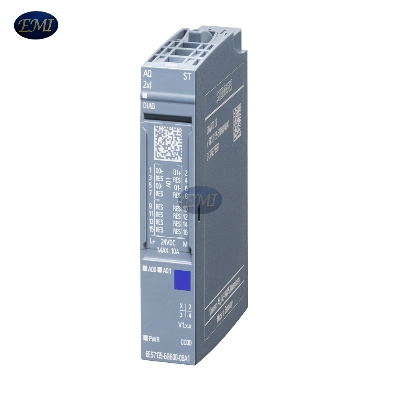
6ES7135-6GB00-0BA1 SIMATIC ET 200SP high quantity Analog output
module PLCAnalog output modulesOverview2 and 4-channel analog
output (AQ) modulesApart from the standard type of delivery in an
individual package, selected I/O modules and BaseUnits are also
available in a pack of 10 units. The pack of 10 units enables the
amount of waste to be reduced considerably, as well as saving the
time and cost of unpacking individual modules.For different
requirements, the analog output modules offer:Function classes
Standard, High Feature and High-SpeedBaseUnits for single or
multiple-conductor connection with automatic slot codingPotential
distributor modules for system-integrated expansion with potential
terminalsIndividual system-integrated potential group formation
with self-assembling voltage busbars (a separate power module is no
longer required for ET 200SP)Option for connecting current and
voltage actuatorsClear labeling on front of moduleLEDs for
diagnostics, status, supply voltage and faultsElectronically
readable and non-volatile writable rating plate (I&M data 0 to
3)Extended functions and additional operating modes in some
casesOversampling operating mode (n-fold equidistant output of an
analog value within one PN cycle and thus the precisely timed
output of an analog value or a sequence of analog
values)Isochronous mode (simultaneous equidistant output of analog
values)Output of substitute value in the event of interruptions to
communication (shutdown, output adjustable substitute value, or
keep last value)Calibration during runtimeRe-parameterization
during operationFirmware updateDiagnostics of wire break,
short-circuit, overflow, underflowValue status (optional binary
validity information of the analog value status in the process
image)Supports the PROFIenergy profileOptional accessoriesLabeling
strips (film or card)Equipment labeling plateColor-coded label with
module-specific CC codeShielding terminalA quick and clear
comparison of the functions of the AQ modules is offered by the TIA
Selection Tool.ApplicationThe analog output modules enable analog
actuators (proportional valves, drives, etc.) to be controlled.
DesignUsable BaseUnits (BU)BaseUnits with an appropriate
number of terminals are available for single or multi-conductor
connection.All variants that correspond to the BU type of the I/O
module used can be used as BaseUnits (see Selection and ordering
data). The BaseUnits that can be used for the respective module are
noted on the front side of the module.Potential distributor
modulesWith the new potential distributor modules for SIMATIC
ET 200SP, additional potentials required within an ET 200SP
station can be set up quickly and in a space-saving manner. Due to
the free combinability of PotDis-BUs and PotDis-TBs, the potential
distributor modules allow a large number of design variants and
thus simple adaptation to individual needs. Within the station,
existing potentials can be multiplied or even new potential groups
can be formed. With 36 terminals per 15 mm width, the PotDis
modules require very little space without compromising on the
conductor cross-sections (maximum 2.5 mm²). They allow the
connection of voltages up to 48 V DC with a maximum current
carrying capacity of 10 A, and with the PotDis-TB-BR-W even up
to 230 V AC/10 A as well as the possibility to connect a
protective conductor.Typical applications for the PotDis modules in
connection with AQ modules are, for example, the supply of supply
voltage for sensors.Potential group formationA light BU separates
the self-assembling, internal voltage buses (P1, P2, AUX) and thus
opens a new potential group. The supply voltage of a potential
group must be fed in at the light BU of this potential group.A dark
BU forwards the supply voltage of the adjacent light BU on the left
via the self-assembling voltage buses P1, P2 and AUX. A new infeed
is therefore only required on the next light BU to the right. The
setting of a further light BU is required whenevera new potential
group is to be formed (for example, for isolating the supply
voltage from module groups) orthe maximum current simultaneously
required by the potential group exceeds the permissible limit of
10 A.Color identification of the terminalsThe potentials at
the terminals of the BaseUnit are defined by the inserted I/O
module in each case. To prevent wiring faults, the potentials of
the terminals can optionally be identified by means of
module-specific color-coded labels. The color-coded label that
matches the respective I/O module is defined by the color code CCxx
of the I/O module. This color code is also printed on the front of
the module.In BaseUnits with the additional ten internally jumpered
AUX terminals, these can also be identified with color-coded
labels. For the ten AUX terminals, color-coded labels are available
in red, blue, and yellow/green.LabelingLabeling stripsLabeling
strips can be inserted on the front of the interface modules or I/O
modules and individuall


Quality New 6es7135-6GB00-0ba1 Simatic Et 200sp Electronic Analog Output Module PLC products, provide good price New 6es7135-6GB00-0ba1 Simatic Et 200sp Electronic Analog Output Module PLC from .
Larger photo of New 6es7135-6GB00-0ba1 Simatic Et 200sp Electronic Analog Output Module PLC
Related products about New 6es7135-6GB00-0ba1 Simatic Et 200sp Electronic Analog Output Module PLC
-
 Waste Tyre Plastic Recycling Machinery Machine Tire Crusher Production Line Rubber Crumb Grinding Machine Equipment Tire Shredder
-
 Stretch Plastic Blowing Pet Bottle Making Blow Molding Machine Bottles Stretch Automatic Pet Bottle Blowing Machine
-
 Waste Plastic Pet Bottle, Water Bottle Flake, PP/HDPE/LDPE PE Film Jumbo Woven Bags Plastic Crusher Machine, Plastic Crushing Washing Recycling Machine
-
 Type 2 Wall-Mounted Electric Car Charging Station 7kw /11 Kwelectric Vehicle Charging Station Home Wallbox AC EV Charger Single Phase or 3three Phase
-
 G-View G12W Wholesale Auto Car LED Headlight Bulb High Power H13 H11 9005 H7 H4 Car LED Headlights LED Car Lights
-
 New Design Porcelain Round Plates Dinner Set for Wedding and Banquet
-
 China 2023 New Design Super Soft 100% Polyester Microfiber Knitted Oversized Decoration Hoodie Blanket
-
 Handmade Art Creative Materials Thickened White Paper Cup DIY Disposable Handmade Colored Paper Cup


