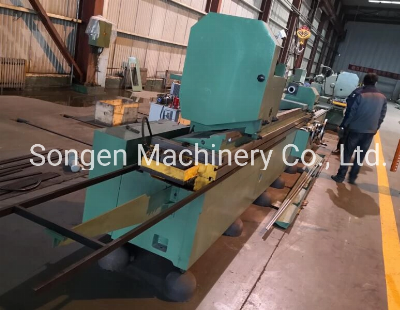
General description:This model ECG630 x 4000 heavy-duty external
cylindrical grinding machine carries 3000 KG workpiece. It features
a simple and compact structure, T-shaped layout, and easy
operations. It is a general-purpose grinding machine used for
grinding external cylindrical/tapered surfaces
on axis-symmetrical work pieces. Due to its easy operations
and efficiency on performance and productivity, this external
cylindrical grinding machine is widely used in the single-piece,
small-batch or mass production in workshops.Main structuresThis
external cylindrical grinding machine consists mainly of the
machine bases, the worktable, the work head, the tailstock, the
grinding wheel head, the cross feeding mechanism, the hydraulic
system, the cooling system, the lubrication system and the
electrical system. 1. Machine basesHeavy machine base of
T-shaped layout on this cylindrical grinding machine is made of
high-density and fine-grained grey cast iron through the resin sand
casting process. It is properly heat-treated to eliminate its
internal stress to the minimum so that it is free from distortion
in the long-term operation. It provides a rigid base to support all
the units and features high stiffness and adequate length to
support the worktable on all positions. 1.1 Grinding wheel head
base & bed waysa) "V-Flat" type bed ways for optimum stability and
rigidity;b) Hydrostatically-lubricated bed ways provide almost
friction-free movements for the grinding wheel head, ensuring the
long-term stable & precision feedings. The lubrication pressure
stabilizer is mounted in the rear of the grinding wheel head. The
lubrication pressure in each oil cavity on the bed ways can be
adjusted independently in order to achieve the same floated up
height for the grinding wheel head along the bed ways.1.2
Worktable base & bed waysa) "V-Flat" type bed ways for optimum
stability and rigidity;b) Hydrostatically-lubricated bed ways
provide almost friction-free movements for the worktable mounted on
top of it. The oil cavities evenly spread along the length of the
bed ways, with each oil cavity can have its pressure independently
adjusted to achieve the same floated up height for the worktable
along the bed ways;c) Stainless steel made telescopic covers will
be fitted on both ends of the worktable to prevent the swarf from
clogging the engagement between the worktable and the bed ways.2.
Worktablea) It consists of the upper table and the lower table
which are positioned and assembled with positioning pins and
pressing bars at the both ends. The upper table swivels
counter-clockwise up to 2 Degrees and clockwise up to 1 Degree.
When the upper table is swiveled, its swiveling angle is observed
on the graduated scale. For micro adjustments for the angles, the
dial test indicator can be used;b) The worktable longitudinal
movements can be actuated steplessly at variable speeds by the
hydraulic forces or be driven with hand wheel. The engagement
between the lower table and the bed ways is
hydrostatically-lubricated to obtain almost friction-free movements
for the worktable, thus the machine's operation life-span is
greatly extended. The oil cavities evenly spread along the bed
ways, during grinding operations, receive pressured lubrication to
slightly float up the worktable to an even height in the
longitudinal direction. The lubrication pressure of each oil cavity
can be adjusted independently to ensure the worktable to be floated
up to the same height throughout its whole length;c) Underneath the
lower worktable, the hydraulic cylinder and the gear rack are
furnished for worktable's hydraulic driving and hand-wheel
driving.3. Work heada) The work head is box type and fixed on the
worktable with two M30 bolts. A Metric #80 dead center is inserted
in its spindle nose bore to offer very rigid supporting for
workpieces in order to improve the grinding performance. It is
usually located at the left end of the worktable, but can also
be moved to any desired positions along the longitudinal direction
on the worktable by driving the hexagonal pin;b) A
variable-frequency motor is mounted on the work head to drive the
spindle, thus the spindle speeds can be conveniently adjusted in a
range of 10 - 100 RPM through operating the variable-frequency
converter which drives the spindle motor. A tailstock mounted on
the worktable holds the work pieces together with the work head. It
can be moved and located on any position along the
worktable;c) The work head spindle speeds are infinitely
variable within three speed phases for easily selecting suitable
speeds according to the material of workpieces to be ground. The
shift between different speed phases is carried out by changing the
set of engaging pulleys at the rear of the work head. An interlock
safety switch is furnished on the pulley hood which, when the
pulley hood is opened, will shut off the power supply to the work
head motor to ensure the personnel safety.4. Tailstocka) The
tailstock is


Quality ECG630X4000 External Cylindrical Grinding Machine products, provide good price ECG630X4000 External Cylindrical Grinding Machine from .
Larger photo of ECG630X4000 External Cylindrical Grinding Machine
Related products about ECG630X4000 External Cylindrical Grinding Machine
-
 Waste Tyre Plastic Recycling Machinery Machine Tire Crusher Production Line Rubber Crumb Grinding Machine Equipment Tire Shredder
-
 Stretch Plastic Blowing Pet Bottle Making Blow Molding Machine Bottles Stretch Automatic Pet Bottle Blowing Machine
-
 Waste Plastic Pet Bottle, Water Bottle Flake, PP/HDPE/LDPE PE Film Jumbo Woven Bags Plastic Crusher Machine, Plastic Crushing Washing Recycling Machine
-
 Type 2 Wall-Mounted Electric Car Charging Station 7kw /11 Kwelectric Vehicle Charging Station Home Wallbox AC EV Charger Single Phase or 3three Phase
-
 G-View G12W Wholesale Auto Car LED Headlight Bulb High Power H13 H11 9005 H7 H4 Car LED Headlights LED Car Lights
-
 New Design Porcelain Round Plates Dinner Set for Wedding and Banquet
-
 China 2023 New Design Super Soft 100% Polyester Microfiber Knitted Oversized Decoration Hoodie Blanket
-
 Handmade Art Creative Materials Thickened White Paper Cup DIY Disposable Handmade Colored Paper Cup