IntroductionThe production
line is mainly used in drilling and sawing of H beam, U beam
which are applied in the fields, such as construction, bridge,
boiler, stereo garage,offshore drilling platform and, specially, in
steel structure which requires high precision and easy operation.
This is machine is necessary for steel structure fabrication.
Structure
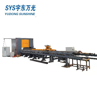
and configurationThe combination production line consists
of drilling line and Band Saw, two pairs of
infeed in and outfeed conveyors ,and one CNC control
device and two side conveyors, along with electrical system,
hydraulic system, air cooling and lubrication.The combination line
adopts Z form arrangement that the drilling line and the band saw
are installed in parallel and connected by transverse conveyor.
Each of the two infeed conveyors equips a NC feeder dolly
with servo motor on the datum side and side push device to push the
workpiece to the datum side; the drilling line equips an automatic
transverse conveyor to upload workpiece; the outfeed conveyor
equips roller to move the workpiece out of the process zone and to
the transverse conveyor. In the working process, the personal
should lift the workpiece to the automatic transverse conveyor,
after the workpiece is uploaded to the infeed conveyor from the
transverse conveyor, the side push moves the workpiece to to the
datum side, and the dolly moves the workpiece to the processing
zone to drill, after the drilling, the roller moves the workpiece
to the outfeed conveyor, the transverse conveyor which
connects drilling line and band saw moves the workpiece from the
outfeed of the drilling line to the infeed of the band saw to cut
the workpiece, after the cutting the workpiece is downloaded to the
outfeed, and the transverse conveyor of the band saw moves
the workpiece out of the processing zone.The process sequence is
from drilling to cutting, the long workpiece which is meant to
process into several pieces can be drilled integrally and then cut
in to pieces. The transverse conveyor between two lines in Z form
arrangement can can adjust the process speed. The Z form arrange
let these two lines work both together and separately, when one of
them is in maintaining the another line can work
independently.
ConfigurationThe combination line line includes dolly, dolly
track, feed conveyor, feeding line, drilling line, band
saw, electrical control system, hydraulic system, air cooling
system, lubrication and etc.
Terms to explain1. Dolly:
driven by servo motor with gear box via rack and pinion, the
workpiece is clamped by the jaw in order to lengthwise infeed and
positioning.2. Dolly track: bear dolly to infeed, this track can by
customized. 3. Feed conveyor: consist of
infeed conveyor and outfeed conveyor to bear and output the
workpiece.4. Feeding line: this transverse line consists of four in
feed frames to automatically upload workpiece.5. drilling line: 3D
drilling machine has three drilling heads with spindle. The side
drilling head has vertical positioning, and vertical drilling head
has radial positioning. 6. Band saw: equip two-pillar-closed
structure, linear guide, possess high stiffness and efficiency. 7.
Hydraulic system: equip with oil tank, low pressure pump set,
cooler, main valve block and other control valve unit. 8.
Electrical control system: with PLC and computer, two sets of it.
9. Hydraulic system:control hydraulic movements and support
hydraulic power.10. Air cooling system:adopt mist cooling for
drilling line, band saw adopts water cooling. 11. Lubrication:
VERSA lubricating system, support linear guide, guide screw,
bearing and etc., some other parts of this line apply artificial
lubricating.ModelSWZ1508SpindleSpindle Axis3 Spindle
taperBT40 Spindle rotation speed(r/min)Stepless speed
regulation200~3000 Max. hole diameter(mm)Fixed Side, Moving
SideΦ40(High Speed) Intermediate Unit 3
Positioning CNC axis moving speedm/min0-10m/min 3 feed
CNC axis moving speedm/min0-5m/minMotor powerSpindle motor power
(KW)3*11 Servo motor power of 3
Pcs feeding Axis(KW)3*2 Servo motor power
of 3 Positioning Axis (KW)3*1.5Feeding Trolley Feeding
trolley servo motor(KW)5 Maximum feeding
speed(m/min)20m/min Maximum feeding weight(Tonnes)10TControl
systemCNC SystemJapan YOKOGAWA PLC CNC Axis
Quantity7Hydraulic systemMax. Hydraulic Pressure
(MPa)7.5 Motor power(KW)5.5Cooling systemNo. of
Nozzle3 Pressure of compressed air
(Mpa)≥0.5 Cooling wayInternal Cooling & External CoolingTool
Magazine(optional)Tool Magazine Quantity3 Tools quantity for
each Magazine4 PiecesMarking unit(optional)No. of Characters36
Characters Characters SizeΦ10 mm Imprinting
Depth0.8~1.5mm Position servo m


Quality CNC Drilling Machine for H Beam Sunshine products, provide good price CNC Drilling Machine for H Beam Sunshine from .
Related products about CNC Drilling Machine for H Beam Sunshine
-
 Waste Tyre Plastic Recycling Machinery Machine Tire Crusher Production Line Rubber Crumb Grinding Machine Equipment Tire Shredder
-
 Stretch Plastic Blowing Pet Bottle Making Blow Molding Machine Bottles Stretch Automatic Pet Bottle Blowing Machine
-
 Waste Plastic Pet Bottle, Water Bottle Flake, PP/HDPE/LDPE PE Film Jumbo Woven Bags Plastic Crusher Machine, Plastic Crushing Washing Recycling Machine
-
 Type 2 Wall-Mounted Electric Car Charging Station 7kw /11 Kwelectric Vehicle Charging Station Home Wallbox AC EV Charger Single Phase or 3three Phase
-
 G-View G12W Wholesale Auto Car LED Headlight Bulb High Power H13 H11 9005 H7 H4 Car LED Headlights LED Car Lights
-
 New Design Porcelain Round Plates Dinner Set for Wedding and Banquet
-
 China 2023 New Design Super Soft 100% Polyester Microfiber Knitted Oversized Decoration Hoodie Blanket
-
 Handmade Art Creative Materials Thickened White Paper Cup DIY Disposable Handmade Colored Paper Cup