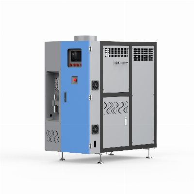
HVE series heat pump vacuum evaporatormodel:HVE-P249Daily
processing capacity:MAX 250LManufacturer: Liheda (Dongguan)
environmental protection equipment Liheda (Dongguan)
Environmental Protection Equipment Co., LtdSewage Treatment
Equipment Based on the Combination of Heat Pump Technology and
Vacuum Technology -- Heat Pump Low Temperature Evaporator1st Floor,
Building 6, Songyuan Innovation Technology City, Junda West Road,
Dongkeng Town, Dongguan City, Guangdong Province Wang
Dewei 13829249131 Technical
features:Processing capacity of water-based
liquid:250L/24hDistillation chamber material (sewage
contact):SUS304(Available in 316 2205 2507 )Cooling chamber
material (distillate contact):SUS304Input power voltage:380V
50/60HZ Three phase four wire five wire system (grounding
wire) 5.8KWInput compressed air:Dry and clean compressed air above
5KGSheet metal construction:Carbon steel powder sprayingHeating
heat exchanger:SUS316coilEvaporation type:Heat pump low-temperature
evaporationEvaporation conditions:-0.92KPA-0.097KPA
temperature25-40ºCEvaporation temperature:25-40ºCSteam
separator:SUS304DemisterHeating and cooling technology:Heat pump
circuitHeat pump compressor:vortexcryogen:R22Vacuum system:Liquid
ejectorOperation control:PLC and HMI intelligent control and 4G
remote monitoringNoise:68dB (A) measured at 1M from the mechanical
surface and 1.6M from the ground Nominal performance (factory
test performance):The data in the following table are the
performance indicators obtained by using tap water as process
water.power supplyunit380V 50/HZMaximum output of
evaporation effluentL/24h250±10%Absorbed powerKW2.25±10%Heat
generated by radiatorKW2.25±10%Air flow around radiatorGood
ventilationHeat dissipationTemperature at saturated
evaporationSewage: 37 ºC± 10% Steam: 36 ºC± 10% Distillate
temperature: 28 ºC± 10% Function description: an evaporator
(temperature 25-40 ºC) for treating water-based liquid based on
vacuum and heat pump technology;3.1,technological
process: The liquid to be treated is sucked into
distilling chamber D01, and vacuum is generated in the distilling
chamber under the action of G01. The feedback signal from EV01
liquid level sensor is sent to PLC, and the PLC controls VM02 to
open and close. The bottom of the distillation chamber consists of
a coil heat exchanger E01. The refrigerant R134A of the heat pump
circuit flows into the heat exchanger E01. The liquid to be treated
contacts the E01 heat exchanger and is heated to boil. The steam
rises through the demister. The refrigerant generated by the steam
and E02 exchanges heat and cold through the circulating water in
G02 and F01. The distillate and non condensable gas are taken
together and sent to the storage tank D02 by G01. The distillate is
discharged through overflow, and the non condensable gas and liquid
are discharged together. The concentrate is discharged through
valves VM01 and G03 after the cycle is completed;3.2,vacuum
system The vacuum system is composed of a multi-stage
centrifugal pump and an ejector. The ejector adopts the Venturi
principle and uses the distillate produced by the evaporator as the
motor power fluid. The efficiency of the vacuum system depends on
the temperature of the motor fluid. The opening of valve VM03 can
destroy the vacuum in the evaporation chamber;3.3,Heat pump
circuit The heat required for evaporating liquid and
the cooling capacity required for condensing steam are provided by
the heat pump circuit. The refrigerant in the gas phase is
compressed by the compressor, flows into the E01 plate heat
exchanger, and releases the heat to the liquid. The refrigeration
after releasing the heat is cooled. The auxiliary fin radiator K02
starts the secondary heat exchange according to the set conditions,
and any excess heat is released to the environment. The liquid
phase refrigerant flows through the filter to the expansion valve.
After throttling, the refrigerant with low temperature and pressure
is generated, which is used to condense the cooling capacity
required by the steam;3.4,Auxiliary liquid Foam inhibitor is
supplied by valve VM04;Options and AccessoriesSerial
Nodescriptionconfigurationremarks1Foam inhibitor liquid shortage
warningStandard configuration 2Original liquid
barrelOptionalStandard configuration of suction
reminder3Concentrate barrelOptionalOptional concentration tank full
reminder4Distillate barrelOptionalOptional distillate full
warning Size, weight, packaging, storage and
handlingtypesize(MM)weight(KG)Unpacked1535*900*1900545
If the equipment needs to be stored for a long time before
installation, it should be kept indoors, in a clean and dry area,
with a temperature range of 5-35 ºC and a relative humidity of 20%
- 80%; The transportation of evaporation requires the help of a
forklift of appropriate length;Ambient conditions, ventilation and
auxiliary coolingCondition TypeWorking conditions10-40ºCNormal0ºC
Quality Hve-P249heat Pump Vacuum Evaporator, 250L/T Negative Pressure Heat Pump Evaporator products, provide good price Hve-P249heat Pump Vacuum Evaporator, 250L/T Negative Pressure Heat Pump Evaporator from .
Larger photo of Hve-P249heat Pump Vacuum Evaporator, 250L/T Negative Pressure Heat Pump Evaporator
Related products about Hve-P249heat Pump Vacuum Evaporator, 250L/T Negative Pressure Heat Pump Evaporator
-
 Waste Tyre Plastic Recycling Machinery Machine Tire Crusher Production Line Rubber Crumb Grinding Machine Equipment Tire Shredder
-
 Stretch Plastic Blowing Pet Bottle Making Blow Molding Machine Bottles Stretch Automatic Pet Bottle Blowing Machine
-
 Waste Plastic Pet Bottle, Water Bottle Flake, PP/HDPE/LDPE PE Film Jumbo Woven Bags Plastic Crusher Machine, Plastic Crushing Washing Recycling Machine
-
 Type 2 Wall-Mounted Electric Car Charging Station 7kw /11 Kwelectric Vehicle Charging Station Home Wallbox AC EV Charger Single Phase or 3three Phase
-
 G-View G12W Wholesale Auto Car LED Headlight Bulb High Power H13 H11 9005 H7 H4 Car LED Headlights LED Car Lights
-
 New Design Porcelain Round Plates Dinner Set for Wedding and Banquet
-
 China 2023 New Design Super Soft 100% Polyester Microfiber Knitted Oversized Decoration Hoodie Blanket
-
 Handmade Art Creative Materials Thickened White Paper Cup DIY Disposable Handmade Colored Paper Cup


